Expert Takeaways
- Detector placement must start with credible release and fire scenarios, not a standard spacing grid.
- Detection mapping tests whether the proposed devices see the right hazards early enough to matter.
- Alarm, suppression and ESD actions require a verified cause-and-effect with controlled bypasses and proof-test records.
A detector shown on a drawing does not automatically create effective coverage. Gas dispersion changes with pressure, release direction, congestion, ventilation, gas density and weather. Flame detection depends on field of view, fuel type, distance and obstructions. The engineering question is not “How many detectors do we have?” but “Which credible events will they detect, and what happens next?”
This guide connects gas detector placement, fire and gas mapping, voting philosophy, suppression logic and emergency shutdown (ESD) integration into one verifiable safety lifecycle.
Why Fixed Detector Spacing Is Not Enough
Rule-of-thumb spacing can support an early estimate, but it cannot prove performance. Two identical process areas can need different detector layouts because one has forced ventilation, a roof pocket or a congested pipe rack that changes cloud movement. Brownfield modifications may also block a flame detector's line of sight or redirect airflow.
A defensible design links each detector to the hazard assessment, release inventory and operating philosophy. Applicable project standards may include IEC 60079 requirements for explosive atmospheres and IEC 61511 lifecycle requirements where safety instrumented functions are involved. The project's legal and technical basis must be confirmed for the facility.
The Detector Placement Workflow
1. Build the Hazard Scenario Register
Use HAZOP, hazardous-area information, equipment data and incident consequences to identify credible gas releases and fires. Record release source, material, phase, pressure, inventory, operating state, ignition potential and required response.
2. Understand Dispersion and Visibility
Review dominant and adverse wind directions, HVAC supply and extraction, low points, roof pockets, congestion and hot surfaces. Computational modelling may be justified for complex, high-consequence areas; simpler scenario-based assessments may be suitable elsewhere.
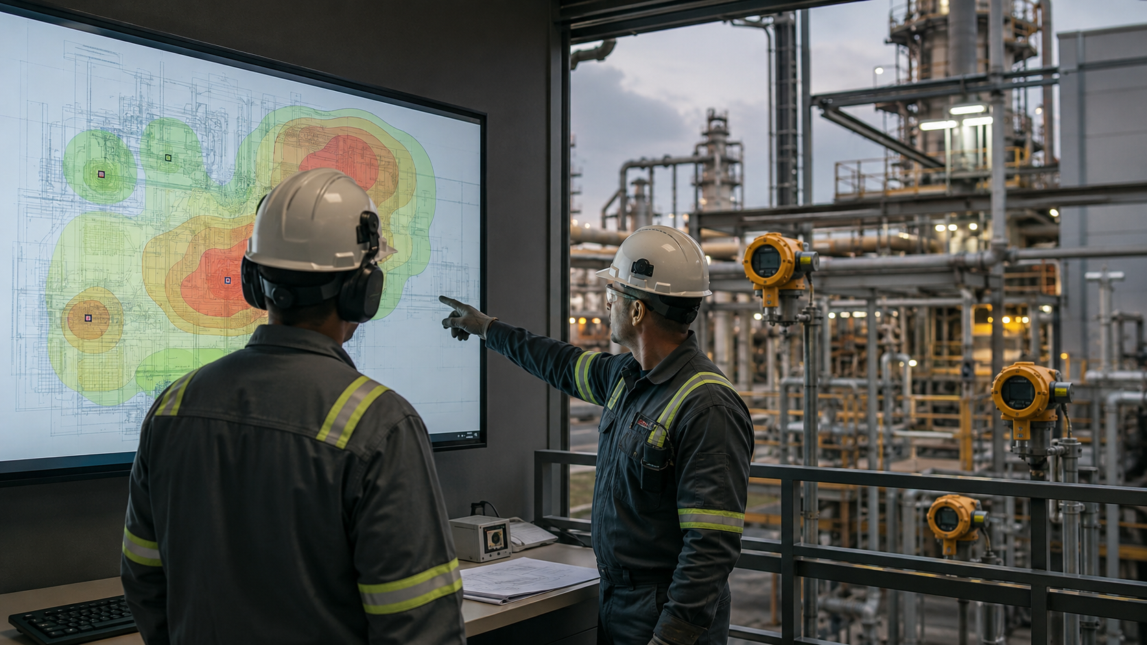
Detection mapping compares device coverage with credible release scenarios and physical obstructions.
3. Match Technology to the Hazard
Point infrared, catalytic, electrochemical, ultrasonic, open-path gas and optical flame detectors solve different problems. Select technology by target substance, oxygen availability, poisoning risk, weather, range, response time, maintenance burden and false-alarm sources.
4. Place for Access as Well as Coverage
A detector must be reachable for calibration, proof testing and replacement without creating a new hazard. Check cable routes, sunshades, vibration, wash-down exposure, condensation, beam alignment and physical protection before finalising coordinates.
Geographic and Scenario-Based Detection Mapping
Geographic mapping measures how much of a defined area or volume falls within assumed detector coverage. It is useful for comparing layout options, but a high percentage can still miss the dominant release sources. Scenario-based mapping asks whether a defined event is detected before it reaches a harmful threshold.
For each scenario, document the devices expected to respond, alarm thresholds, voting requirement, detection time and resulting action. Keep model assumptions, equipment coordinates and revisions traceable so a later plant modification triggers a meaningful review.
Voting, Suppression Logic and ESD Integration
Voting balances availability and protection. A single detector may initiate an operator alarm, while confirmed detection may trigger ventilation changes, isolation, deluge, clean-agent discharge or ESD. There is no universally correct vote: the choice depends on risk, detector independence, nuisance alarm history and required integrity.
The cause-and-effect matrix should define every input state and output action, including fault, inhibit, manual release, abort, reset and loss of power or communication. Where suppression is used, the design must address personnel warning, discharge delay, ventilation shutdown, damper position, agent release confirmation and post-discharge recovery.
Interfaces That Commonly Fail at Commissioning
- Detector tags do not match the PLC, SCADA and cause-and-effect documents.
- Bypasses are not visible, time-limited or alarmed at the operator interface.
- Fail-safe states were assumed but never tested with cable or power faults.
- Suppression outputs are tested in software without proving the final device.
- ESD reset and restart permissives are unclear after a confirmed event.
FAT, SAT and Lifecycle Proof Testing
FAT should verify panel construction, logic, HMI indications, event recording and simulated cause-and-effect. SAT must confirm installed orientation, field response, end-to-end I/O, alarms, voting, final elements and recovery. The handover pack should contain approved drawings, detector settings, certificates, calibration and proof-test procedures, software backups, bypass controls and an inspection schedule.
About the Reader Persona: Safety-Critical Sipho
Sipho is a process safety engineer responsible for proving that the F&G system addresses the facility's real hazards. He wants transparent assumptions, controlled interfaces and test evidence—not a detector count presented as coverage.
Turn Your Hazard Study Into Verified Detection
Mbonyasambe integrates fire and gas detection, suppression interfaces, safety logic, ESD, testing and lifecycle documentation for hazardous industrial environments.
Review Your F&G Coverage